
Bulleid's Unique Patented Chain Driven Valve Gear
The purpose of the valve gear on a steam locomotive is to control the flow, direction and amount, of steam passing into and out of the cylinders, this controls the speed, power and direction of the locomotive. Traditionally steam engines had external valve gear exposed regardless of whether they had either outside cylinders or inside cylinders between the frames. You may be familiar with valve gear design names such as Stephenson’s, Joy or Walschaerts. These valve gear designs are controlled by a series of rods, pivots and links. They were subject to all the grit and muck thrown up from the track and required regular lubrication of all pivots and bearings, which were often not easy to access, especially when the valve gear was mounted inside the frames.

Bulleid’s aim was that steam engines should get nearer to the internal combustion engine that enclosed the working parts and used pump lubrication to keep it all running smoothly. Another advantage of enclosing the valve gear would be the reduced day-to-day maintenance.
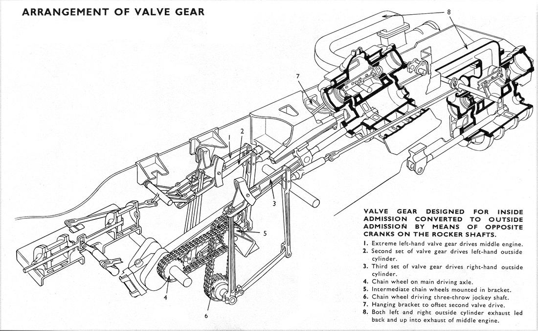
The diagrams below left hand and right hand [click diagrams for a larger version] show the Bulleid patented arrangement which used a Morse chain drive to a three-throw crankshaft. The initial drive was from the centre crank axle to an intermediate sprocket that was horizontal to allow to allow for the rise and fall of the engine on its springs. The shaft of the sprocket had a second sprocket that drove a further chain downwards to a final sprocket mounted on the three-throw crankshaft. Each crank was spaced out accordingly, and operated one set of valve gear, one for each piston valve.
Each valve gear consisted of a vertical eccentric rod that rocked the expansion link controlling the radius rod. From the lower end of the eccentric rod a short forward extension was coupled to the combination via the union link. These elements corresponded to the eccentric rod and crosshead drive of a set of Walshaerts valve gear as per the diagram above.
The final drive to the piston valves was by means of a rocker, which operated the beam between the valve heads. Bulleid used outside admission to avoid the use of high-pressure glands.


All of this valve gear arrangment was contained, including the inside big end, within a 40 gallon oil bath between the frames. It was called an ‘oil bath’ but the depth of the oil was only 2 inches. Reversible pumps, also chain driven, were situated at the bottom of the sump and distributed filtered oil at 20psi by means of pipes to the moving parts.
Experience shows that Bulleid's patented valve gear was very free running when well maintained. The valve events stayed the same for all cylinders when wear developed.
The steam reverser in the diagram above is in fact the early version, use only on the first ten Merchant Navys, with the lever to the valve gear attached to the rod between the two cylinders. The subsequent design used on all the later Merchant Navys including our very own General Steam Navigation and the Light Pacifics, positioned the reverser mounted further back and the drive attached to an extended piston rod. This rod passes straight into the oil bath to make it easier to seal. The reverser used was a development of the Eastleigh and Ashford versions and included elements of both.

© GSNLRS 2016 - 2025, All Rights Reserved.
Member of the Heritage Railway Association,
Bulleid Pacific Locomotive Association
and Mainline Steam Builders Group
Patron: Dr. Alice Bunn OBE (FIMechE FRAeS CEng)